ESP IDF - Delay and Ticks
Introduction
This article is part of a series of contributions on the ESP-IDF framework
I come native to the Arduino environment and have written either C programs for the "desktop", or Arduino for microcontrollers.
Arduino has the charming advantage of bringing along many useful functions in "speaking English", as I call it. One of these functions is called "delay(time)". With this function, certain commands can be executed delayed. A function that can always be useful.
This article shows how the ESP-IDF framework can also implement a delay function and how it works.
Main part
At first, it is important to know how a delay works and the concept of "Ticks" must be known.
What does Tick mean?
A microcontroller does not know from itself how long a second takes or does not know. if it has not installed a RTC, it cannot know. What each processor knows and uses without limitations is its own clocking (measured in Hz). Operating systems as well as FreeRTOS use a temporarily accurate counter variable (called tick) which is defined in Hz. Ticks thus form a defined time unit within systems measured from the last system start. as an example MS Windows 10,000 ticks per second - this then corresponds to 10MHz, FreeRTOS usually has 100Hz, so then has 1 second, 100 Ticks, or 1 tick takes 10ms. How this works more accurately, for example here Look.
What are these ticks used for?
Now it is still necessary to clarify what these ticks are good for. It is already known that with these ticks we can determine how much time has passed since the start of the system and thus we will be able to use our "delay" at the end. But Ticks have an important task in FreeRTOS, because they are responsible for how often the task is planned.
The processor is interrupted at each tick and it is checked whether a task has to be adjusted, i.e. either comes to execution from which suspended Status comes or other. Task States here read or soon simplifies on this blog. But it is important for the following: the higher your tick rate is set, the more frequently the task is interrupted to adjust the task planning.
Between the respective ticks, a task is then processed which was planned by FreeRTOS. In the standard case, therefore, the task has 10ms time, which is not exactly true. The tick time may differ slightly from the setpoint, but in the delay part more :)
Tick rate at ESP by ESP-IDF
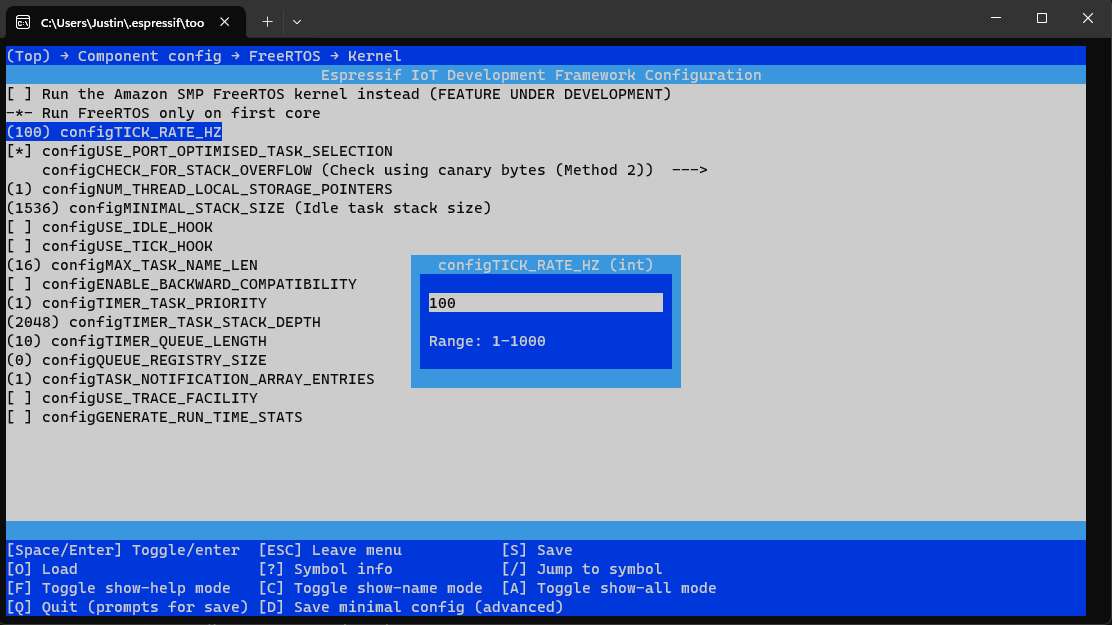
As described above, a tick rate of 100Hz is normally defined. However, it can be that shorter (or longer) time intervals are required so that applications can react faster or get more time for execution, depending on your requirement. In this case, the resolution can be changed by ESP-IDF and between 1Hz and 1000Hz. This allows the interrupt time to be adjusted from 1ms (1000 Hz) to up to 1second. If, for example, a tick rate of 1Hz is used, the counter per second is increased by 1 (the unit of Hertz is n/t -> i.e. 1/s -> or 1 vibration per (/) second if you want to physically decrypt it.
To adjust the frequency, the following command can be executed by IDF:
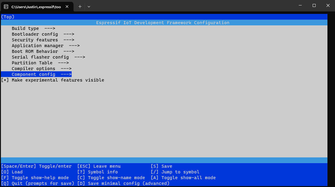
start idf.py menuconfig
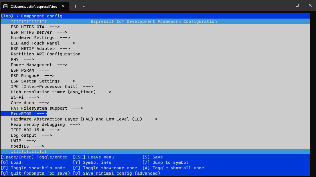
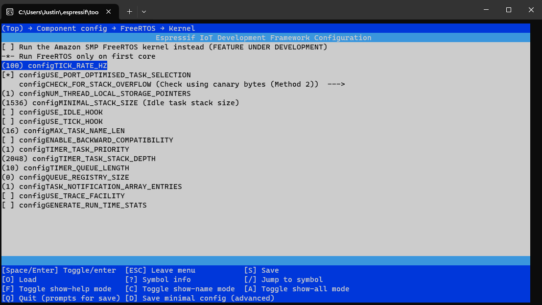
With this command, the following window will be opened. From this menu, the following path must be opened
. > Component Config > FreeRTOS > Kernel > configTICK_RATE_HZ - Now the desired value must be entered. Please note: A higher resolution (short tick time) is not necessarily better!
We're getting the delay from the tick?
Now you should be aware of what it has with the Tick (s) and what it needs in FreeRTOS. We could also work with this to realize delays because we could use the Tick Count with "xTaskGetTickCount" retrieve and then wait until this n is higher. However, this is neither pleasant to implement. For this reason, IDF brings with it a nice funlction, pdMSTOTICKS(ms) called. With this function, we can convert the ticks into ms and thus build a small alias to have a delay function, which is first specified in ms and works above all value-stable! - Because if the Tick Count is turned, the time of a tick will change. So if we were to use ticks as a static value for delays, then there could be unbeautiful effects if the tick count is changed in a device.
The following example shows this behavior
#include <stdio.h>
#include "driver/gpio.h"
#include "freertos/FreeRTOS.h"
#include "freertos/task.h"
#include "esp_log.h"

#define LOG_LOCAL_LEVEL ESP_LOG_VERBOSE

static const char* TAG = "Main";

void app_main(void)
{
    //Set GPIO 2 as Output
    gpio_set_direction(GPIO_NUM_2, GPIO_MODE_OUTPUT);

    while(1)
    {
        ESP_LOGI(TAG, "Turn on LED");
        gpio_set_level(GPIO_NUM_2, 1);
        vTaskDelay(1000);
        ESP_LOGI(TAG, "Turn off LED");
        gpio_set_level(GPIO_NUM_2, 0);
        vTaskDelay(1000);
    }
}
Depending on how high the tick frequency is set, the 1000 ticks are 1 second or 10 seconds. The system is always waiting for 1000 ticks, which could lead us to unpredictable behavior. A circumstance that must of course be avoided. The LED applied to GPIO 2 flashes accordingly, depending on the set tick frequency, differently quickly.
To use a delay, we do the following:
We define the following alias#define DELAY(ms) vTaskDelay(pdMSTOTICKS(ms))
If we now call the DELAY(n) function, a TaskDelay is created with n milliseconds. These are automatically converted into the required ticks. An example based on our test looks as follows:
#include <stdio.h>
#include "driver/gpio.h"
#include "freertos/FreeRTOS.h"
#include "freertos/task.h"
#include "esp_log.h"

#define DELAY(ms) vTaskDelay(pdMS_TO_TICKS(ms))
#define LOG_LOCAL_LEVEL ESP_LOG_VERBOSE

static const char* TAG = "Main";

void app_main(void)
{
    //Set GPIO 2 as Output
    gpio_set_direction(GPIO_NUM_2, GPIO_MODE_OUTPUT);

    while(1)
    {
        ESP_LOGI(TAG, "Turn on LED");
        gpio_set_level(GPIO_NUM_2, 1);
        DELAY(1000);
        //vTaskDelay(1000);
        ESP_LOGI(TAG, "Turn off LED");
        DELAY(1000);
        gpio_set_level(GPIO_NUM_2, 0);
        //vTaskDelay(1000);
    }
}
In this example, the LED flashes to GPIO 2 now every second.
Conclusion
I am still quite new in the field of ESP IDF, however, the functions within the SDK are really diverse and a multiple more powerful than in Arduino - correspondingly steep but also the learning curve. I am currently experiencing a great deal about both the hardware and the software behind ESP, as IDF requires a proper understanding to work with IDF. For example, there is also the possibility to define delays only for certain components of the program (tasks) and to work out other tasks. Within Arduino it was possible to do this earlier on the ESP8266 with the help of SMT by registering a task only for a later time (at the same time, for example here by me).
With FreeRTOS, a delay can be mapped significantly more simply and otherwise the creation of systems is easier. I will try to write down interesting things here again in the next few days and months, so I may also later. a reference if I should forget something ^^^.
Back…